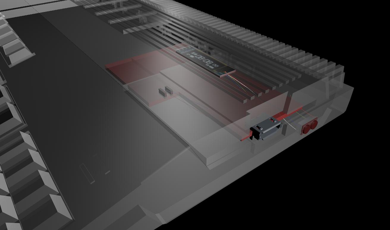
|
A short "Internal Gotek Floppy"
Installation Guide
Hello! This is my attempt at writing a short guide for installing a Gotek drive inside your Amiga 500 or Amiga 1200 computer. It might work for the Amiga 600 as well, but I don't have one and cannot test this.
The goal of this guide is to install the Gotek internally without modifying or even butchering the Amiga case. While the original floppy drive is of course being replaced with the Gotek, and some parts are added inside the Amiga, none of them alter the case in any way. No holes, no marks, no glue!!! The modification is supposed to look as decent and unobtrusive as possible - with the OLED display sitting on top of the case while still being able to use the various Amiga dust covers available. This is the first version of this guide and it will focus on a Gotek drive with two repositioned extra buttons plus OLED display. Maybe I'll add a rotary encoder to it later, but I haven't figured out yet how to actually do this nicely (as in without sticking too far out the case sideways).
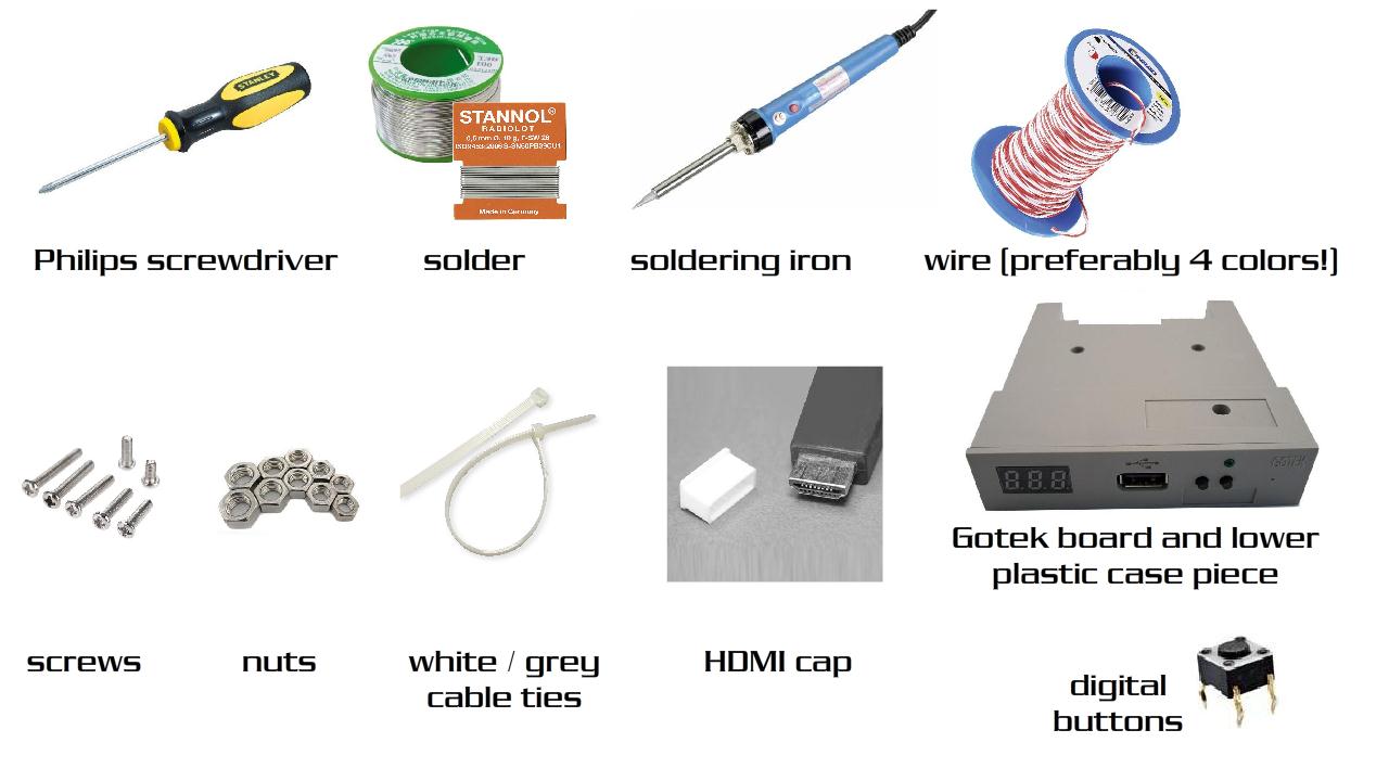
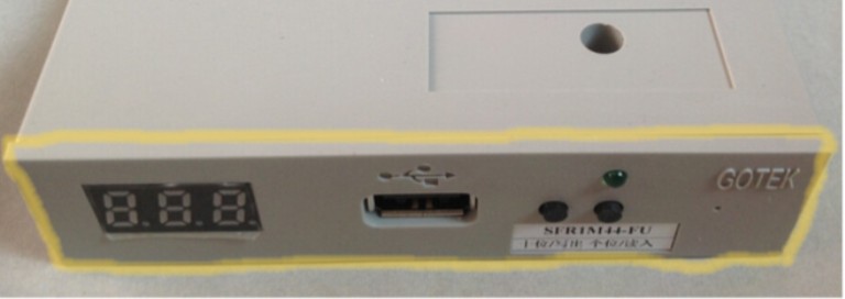
Things you'll need for installing the Gotek, navigation buttons and OLED display:
(all images found via Google image search)
Additional items: Shrink tubes, wire pins (salvage from Gotek LED cables) ...
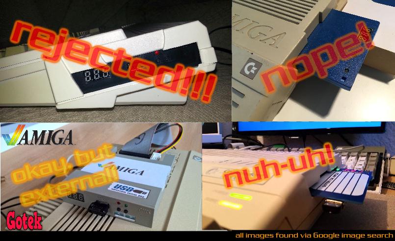
There are so many pictures out there showing an unmodified Gotek shell neatly placed inside an opened up A500 or A1200 case, but when you actually do this and then try to close the Amiga case you're in for a bad surprise - because it does not fit!! A500: If you push the Gotek shell a little further back, then the drive's USB socket and buttons will be misaligned and too far inside for you to reach. It is the main reason why many people start cutting their cases for the drive to fit wholly. (bad idea!) However, there is a really simple workaround: You just need to drill an additional hole inside the Gotek drive's lower shell (a few centimeters to the right of the existing screw hole) and remove the upper shell completely as it is no longer needed. That's it! The drive now fits nicely with the USB socket perfectly centered. We'll worry about the buttons and OLED display in just a moment. The lower shell is held in place along one side via the A500's original screw holding pin that sticks out upwards the case, and another, long screw from the bottom (the A500 already has a hole for this!!) So you'll end up drilling another hole into the Gotek shell but not the Amiga itself. Inbetween the Gotek shell and the Amiga's case floor add as many screw nuts as necessary, thus building a nice holding pillar.
(There is a screw and some nuts
below the Gotek board near where the chip is that leads to the A500
case's screw hole, holding it all in place.
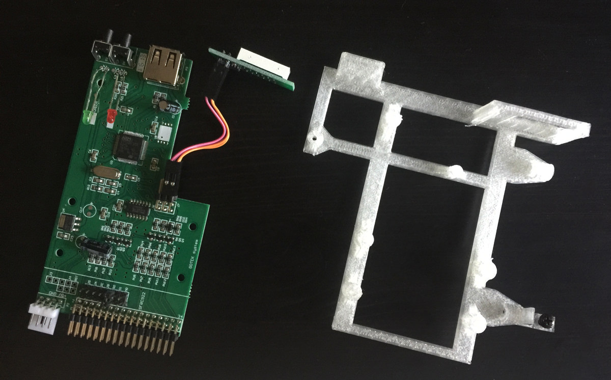
A1200: It's not as simple with the A1200 case because of the drive slit's curved design that gets in the way. This is also a reason why some people decide to just cut it apart (nooooo!). The Gotek's lower shell front panel (the plastic plate with the cutouts for the LED digits, USB port and buttons) gets in the way otherwise. One solution: You can remove the full shell and screw the Gotek board on top of a 3D printed frame, such as this one:
These frames sell on Ebay for around 20 Euros plus shipping and do a very nice job! However, it's a bit on the pricey side for just a piece of plastic and I figured out another solution that works just as fine: Simply cut away / break off the front panel piece of the Gotek's lower shell and treat the edge with a bit of sandpaper for a clean finish. Once you're done, the lower shell does the very same thing the 3D printed frame does: It positions the Gotek perfectly centered inside your case with the original Gotek buttons also still within reach! Awesome! And because the Amiga case wasn't cut, you can't even see the Gotek lower plate from outside.
(Get rid of the upper shell, then cut or break off this entire front panel piece from the lower shell and keep the rest. I used a pair of rough pincers, worked like a charm!)
That's all that needs doing to make the Gotek board fit perfectly, with centered USB port and reachable buttons. Use the metal holder from the original floppy disk drive to screw on the lower shell along the side. And just like the A500 case, there is a hole inside the A1200 case below the Gotek board that you can use to screw it on tightly from below (Drill a new hole into your Gotek's shell for that.) Also use two or three screw nuts inbetween the case floor and the Gotek shell, effectively creating a holding pillar.
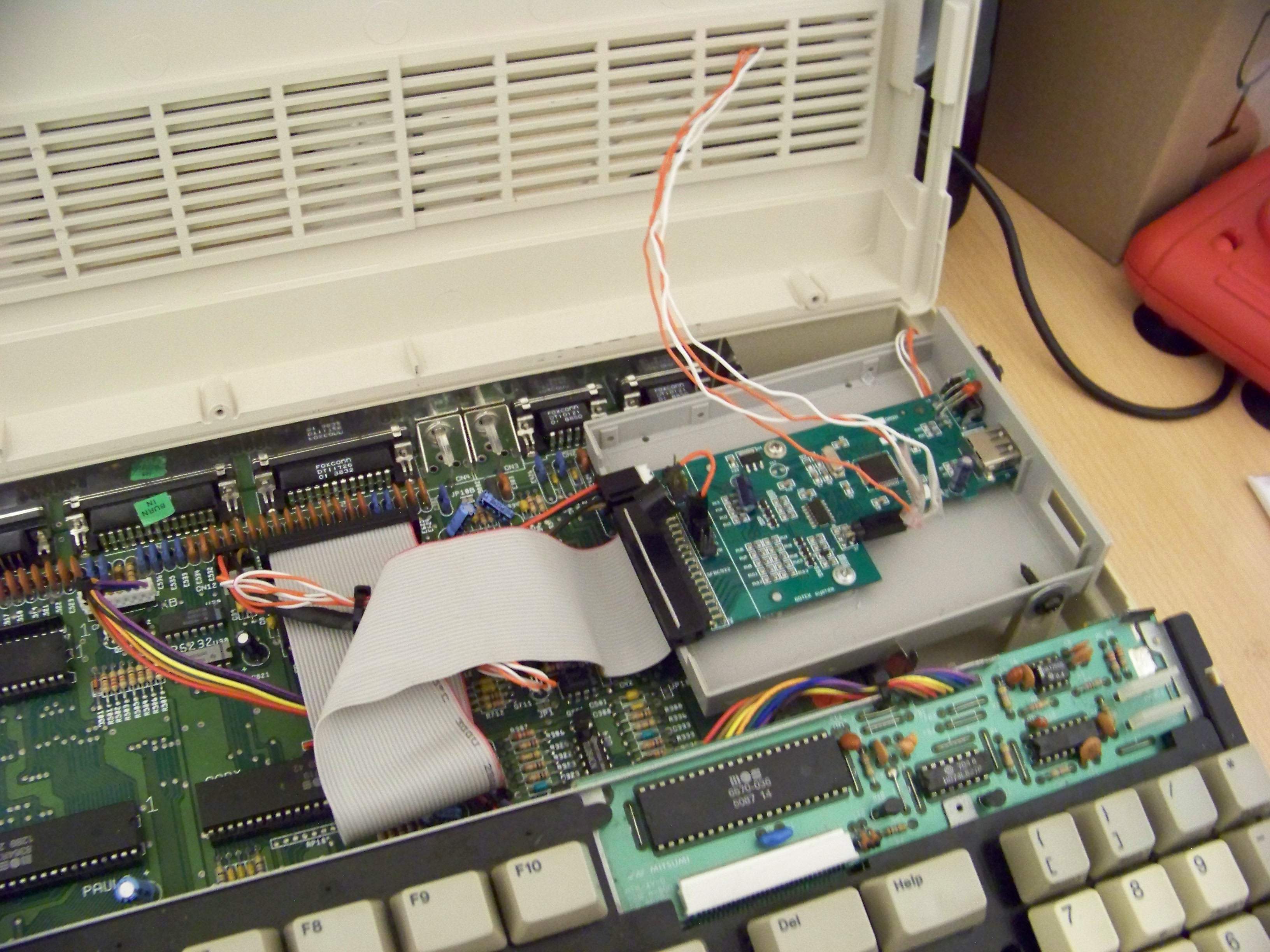
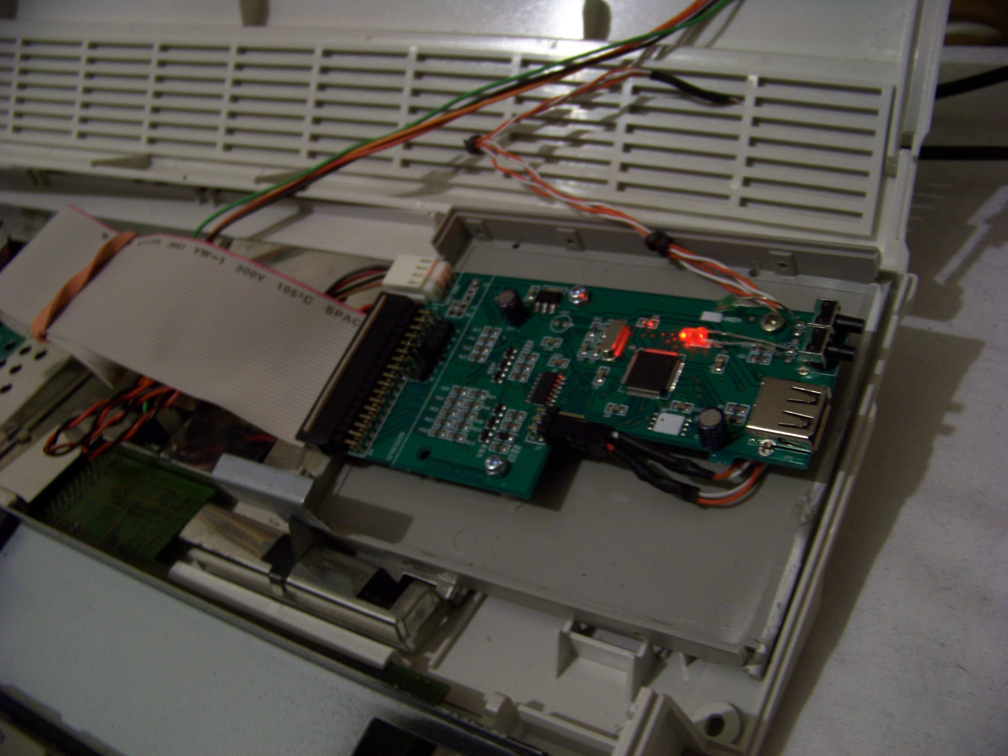
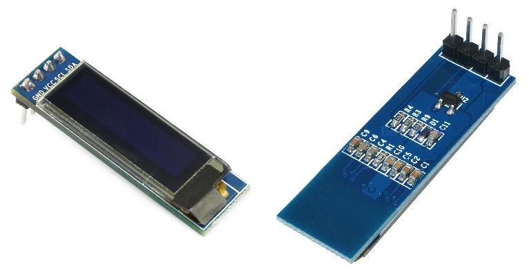
Besides the four wires going from the Amiga motherboard up to the power and drive LED's inside the top part of the case, you can also see four additional wires coming out from the Gotek board's pin outs. They are the wires for the OLED screen and they are fed through one of the venting holes of the case top. When my I2C OLED 128x32 screen arrived, it looked like this:
A500 and A1200: For the screen to sit on top of the case as flat as possible, I had to remove the plastic around the pins and cut them short as closely to the ground as possible. You can also desolder them and then stick the wires directly through the soldering holes. I cut the two wires from the Gotek's original 3-digit LED display into half and extended the cable to about 10-15 centimeters, using the original plastic pins. This is important because in the future, you want to be able to open the case lid without ripping off any of the cables. The rest is pretty self-explanatory. Following Keirf's Flashfloppy hardware guide, you just have to solder the wires accordingly onto the backside of the OLED, the pins are clearly labeled GND, VCC, SCL and SDA. Solder them flat onto the pins so that they lead sideways across the entire backside of the OLED. The actual screen ends a little before the PCB board ends and so you can use a short strip of tape to wrap it around and secure the cables, before bending them carefully around 90 degrees to be fed inside the Amiga case through one of the venting slits. Oh by the way, don't solder on the ending plastic pins before you fed the cable through, because it won't fit otherwise!! Likewise, if you wanted to remove the screen, you'd have to desolder the pins again first.
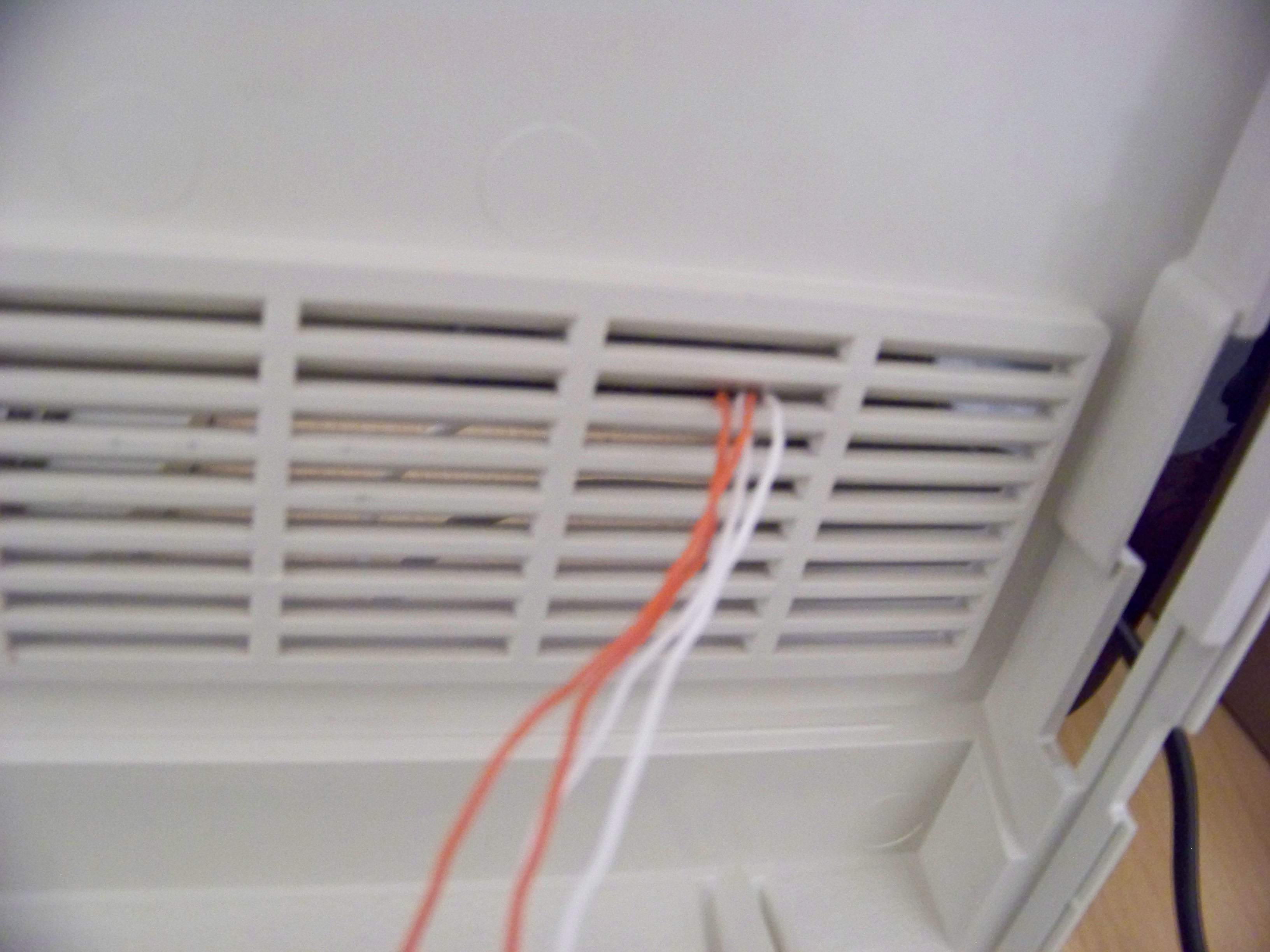
(Depending on where exactly you'd like the screen to be located, you'll have to feed the four wires through a different case gap. I chose the 2nd gap from the bottom and right corners, when looking at the Amiga from the outside. Make sure you run these wires long enough for the case to be opened easily, without accidentally ripping them off!)
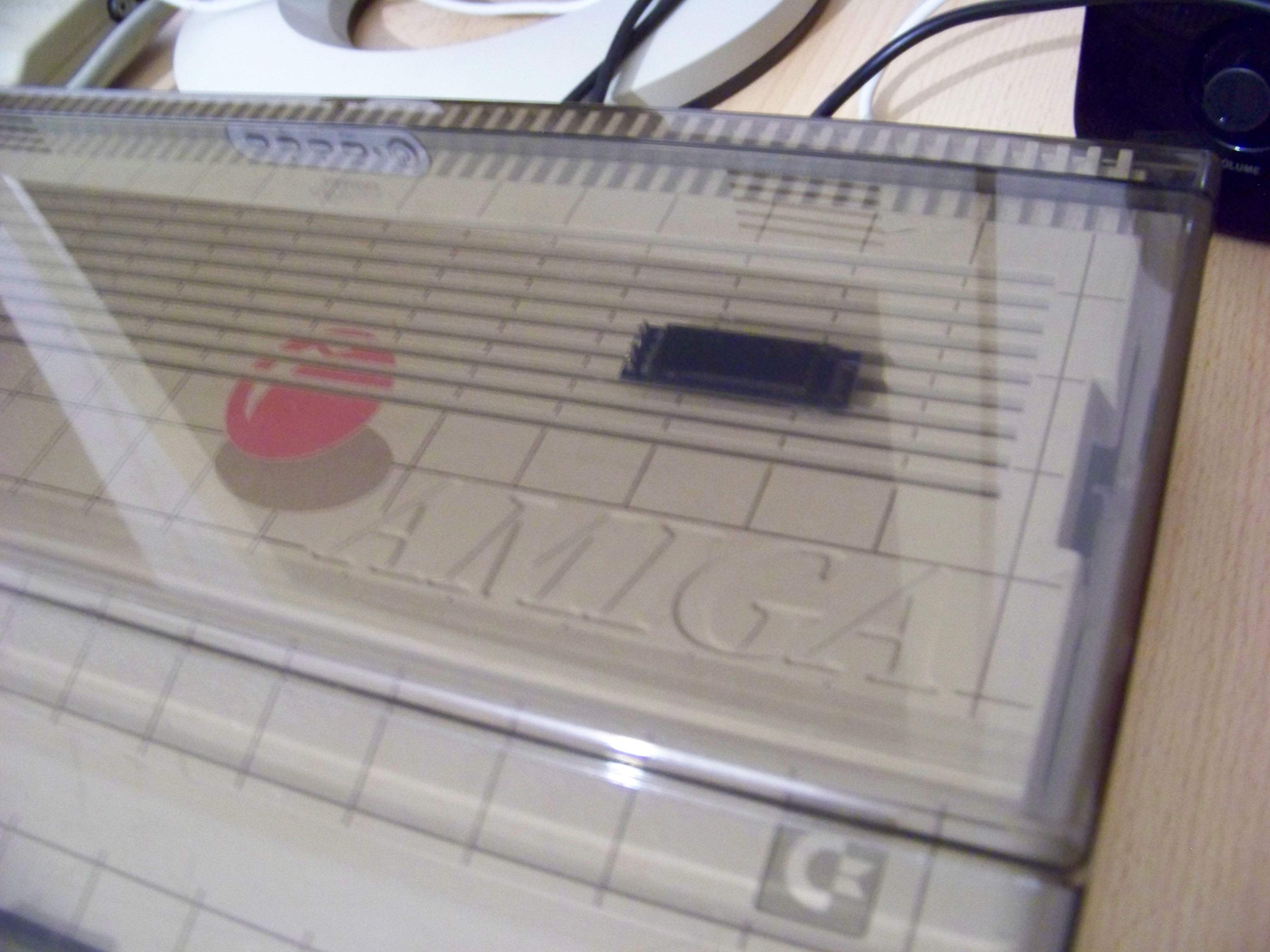
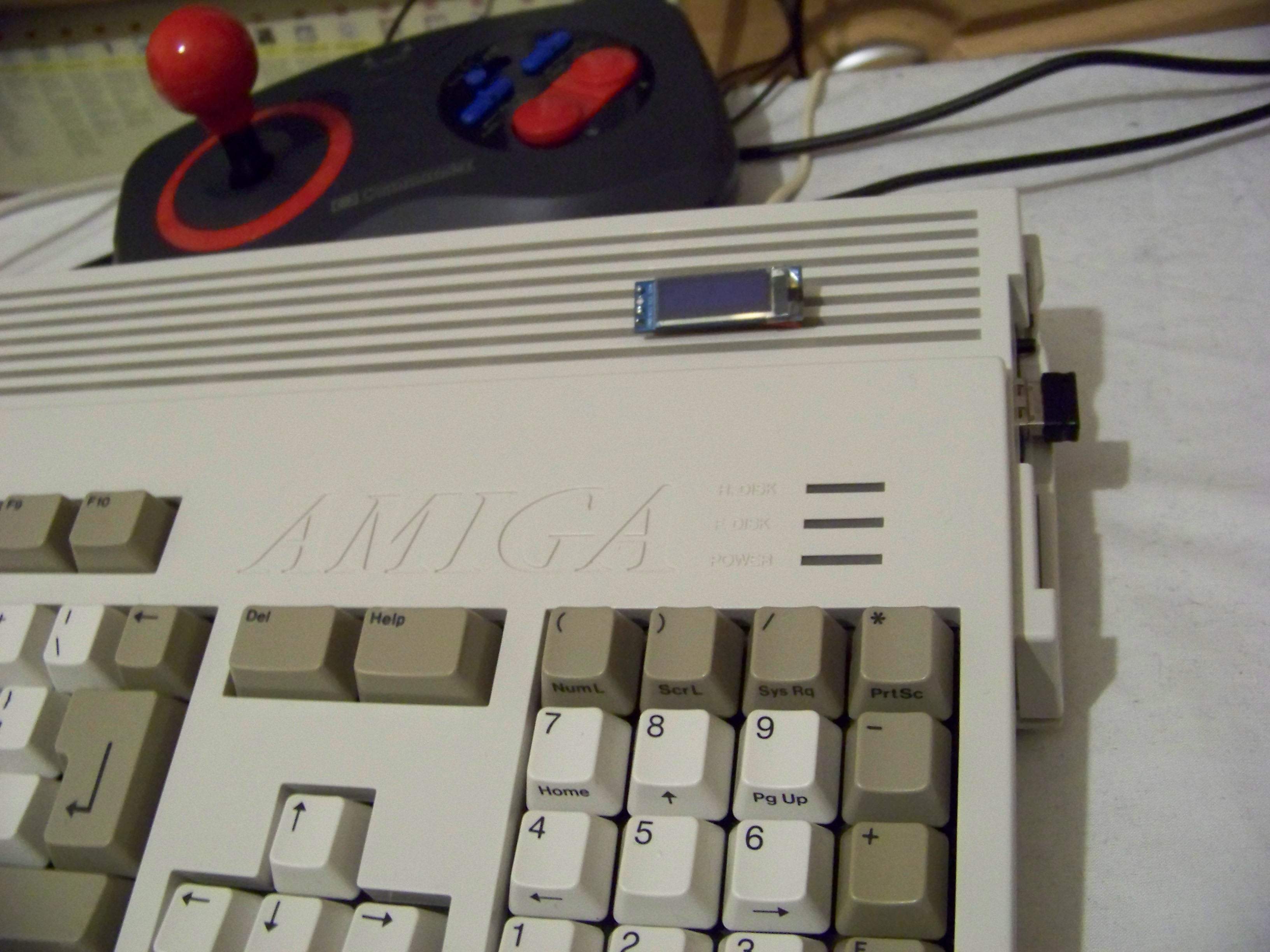
Now that the OLED screen is wired up and connected to the pin outputs of the Gotek board according to Keirf's guide, it is fully operable and sits flat and neatly on top of the Amiga 500 case. You can even put the original hard-plastic dust cover or any soft covers on top without any issues. This is my current set up for both the A500 and A1200. One could easily build a small DIY case to wrap it around the screen for some additional protection. As pointed out by others, there are plenty of printable designs available on Thingiverse, for instance, or tie it carefully to the case using small cable ties (it's just an idea, I haven't tried it yet!). But the fact it looks so darn neat and unobtrusive makes me really happy already.
And here is the Amiga 1200 equivalent:
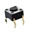
Okay, so the final step to be covered by this short guide are the buttons. I have not added any additional buttons to the Amiga 1200 yet, because the Gotek buttons are easily reachable, although they are not very comfortable. So another solution will just be a matter of time. However with the Amiga 500, we need to relocate the Gotek buttons to somewhere further outside the case so we can press them easily. For this we are going to use one HDMI cap and two of the following digital buttons (available for 23 cents each at Conrad Electronics here in Germany):
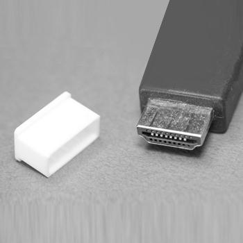
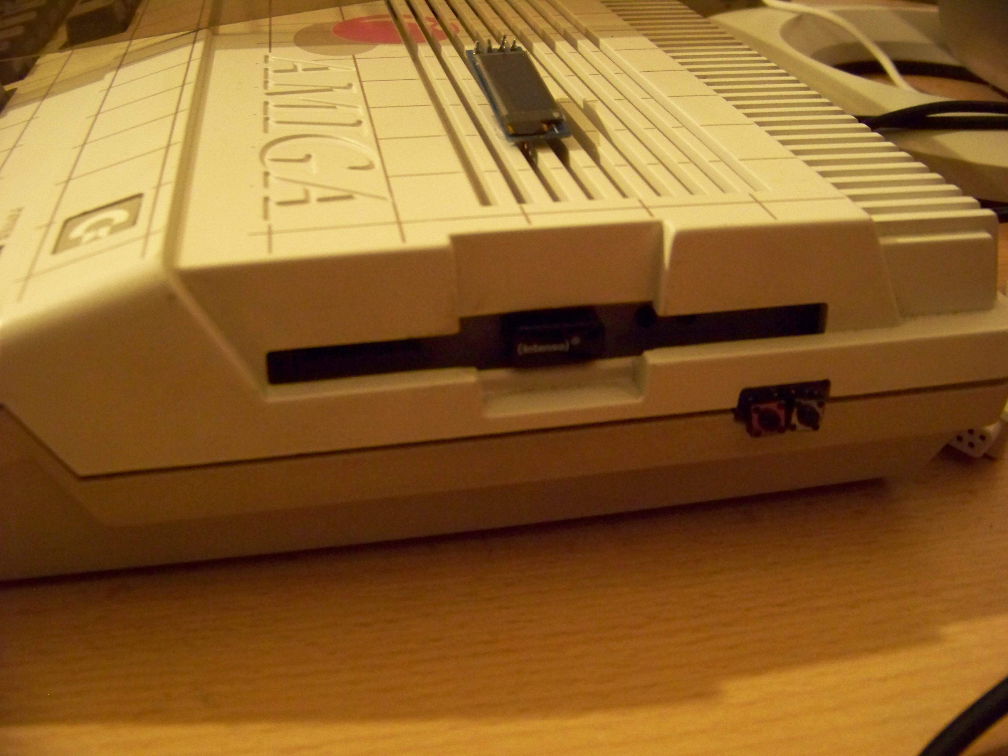
(Maplin UK should stock these digital buttons as well.) The digital buttons are flat and much softer than those found on the Gotek PCB. They come with four pins, but only two are needed, so cut off either the bottom two or top two on both digital buttons. What's the silly HDMI cap for, you ask? Well it turns out, that it fits exactly inside the hole where the Amiga floppy disk drive's eject button used to be. And thanks to the raised edge it does not fall inside the Amiga case when you push it. So we'll drill four tiny holes side by side into the cap's soft plastic (very easy!) and stick the digital button's remaining pins through them, effectively attaching them to the HDMI cap next to each other. You might want to glue the backside of the buttons onto the cap (oh no, I said glue!!), but I didn't do this since it really holds together all by itself. The HDMI cap also holds in place when the Amiga case is closed. When you open it, you can remove the cap just as easily as you inserted it, perfect for those who don't want to leave any marks on the case.
Break off the bottom row of the pins on the two digital buttons, leave the top ones intact. Drill or pierce four small holes into the front side of the HDMI cap, make sure the distance between each hole matches the distance of the pins.
Now push the remaining button pins through the four holes, thus permanently attaching them to the HDMI cap. Now turn the cap around and solder four differently coloured wires to the metal pins from the inside. Careful not to burn the cap with your soldering iron, the fumes smell bad and are not healthy!! Btw. I only had two colors available so I used two red and two white wires, but then it becomes a bit more tricky when attaching them to the Gotek PCB.
And this is what it will look like after. Yay. The four button wires need to be soldered on the bottom side of the Gotek PCB, just below the Gotek's own buttons. The solder points are not seen in the image above but very easily spotted!
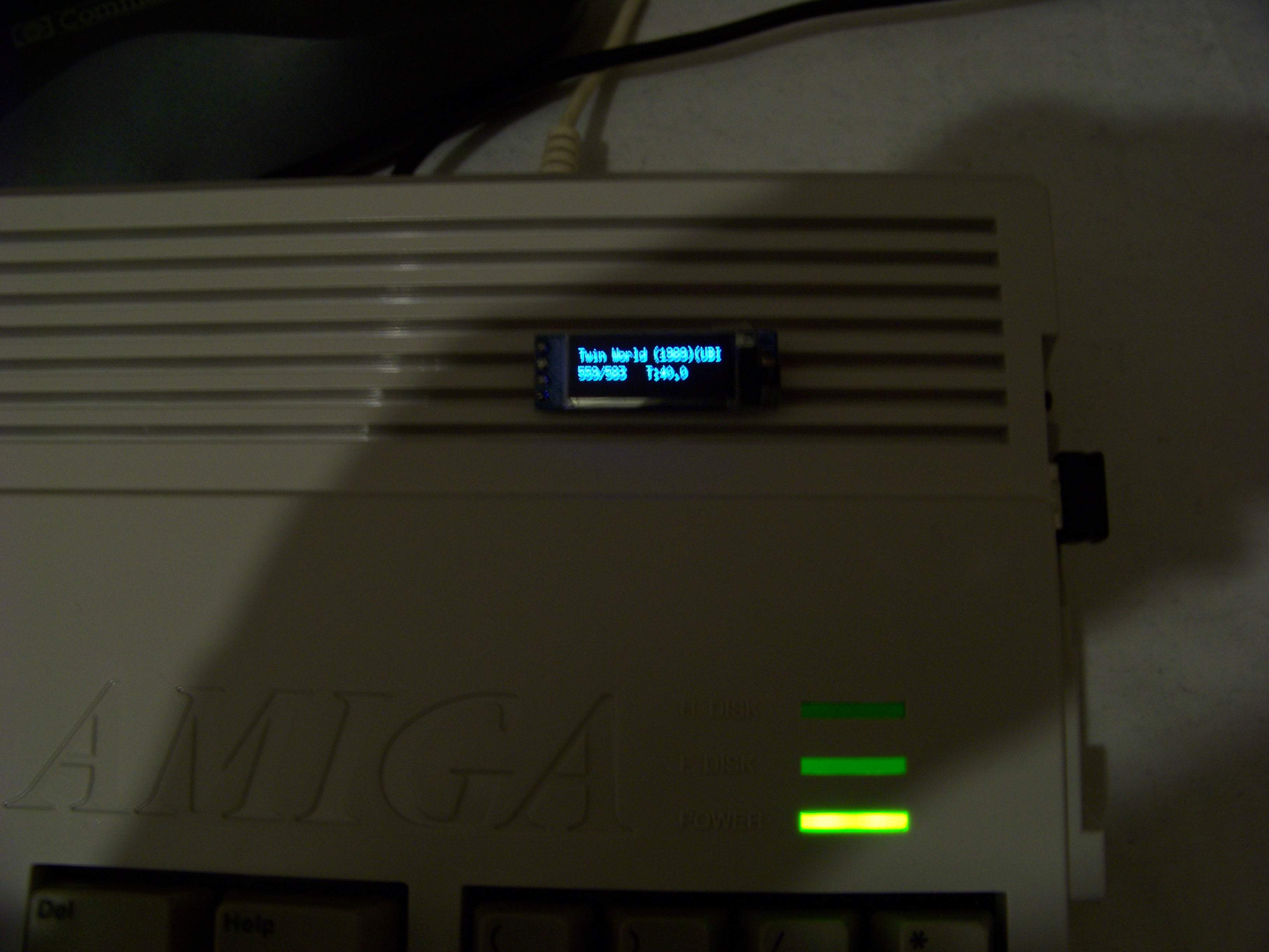
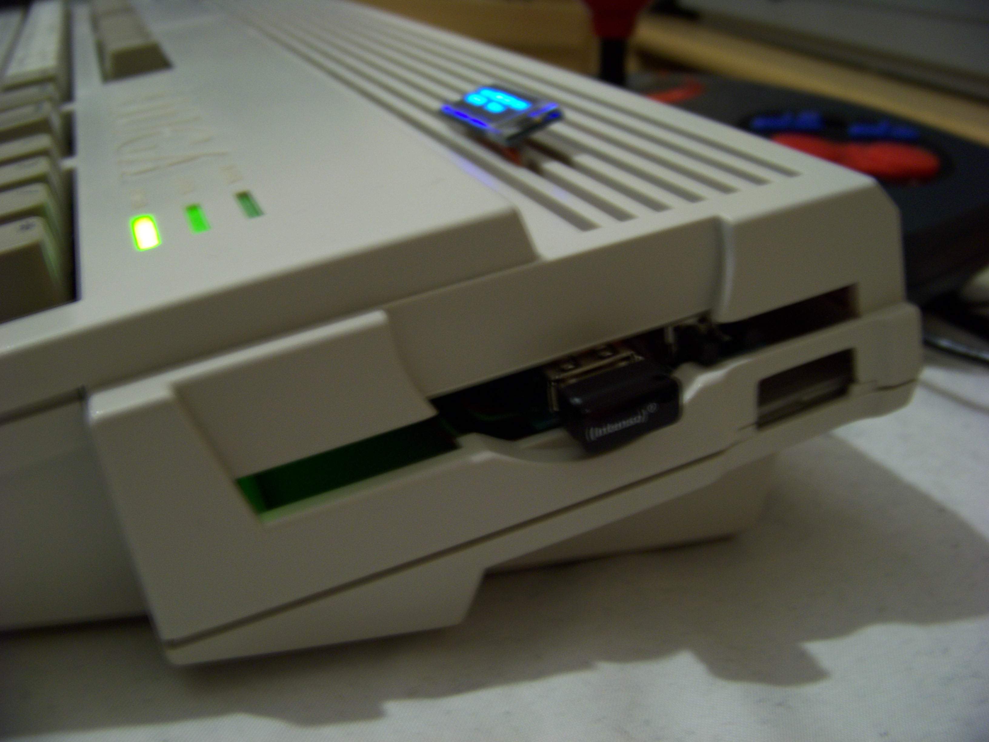
Congratulations!! You now have a fully working Gotek drive with extra buttons (on the A500) AND a fancy OLED screen! (both A500 and A1200). \o/ \o/ And best of it all: You did not harm the original Amiga case at all!!!! \o/ \o/
(Amiga 1200 running Twin World. Slightly shaky camera.)
(Amiga 1200: Neato! I might add some more comfortable buttons to the disk eject button gap, or just refit the eject button itself there, or a rotary encoder or radio wheel for easier navigation, not sure yet!)
Amiga 500: I am very pleased with how this looks. Okay granted, the soft digital buttons are slightly tilted but this looks worse in the photo than it does in reality. The USB stick is a perfect fit and the OLED screen makes all the difference in usability. So much better than the old 3-digit LED display!
Finally, I would like to thank the creator of the Flashfloppy firmware, Keirf aka kaffer from EAB and Jeff, the creator of the HxC firmware (although I don't use it myself, all current firmware development is based on his previous work and therefore should be honoured), as well as all other Amigans around the world for inspiring me to write up this short guide. It is by no means perfect or complete and probably won't be for a long time, but maybe it will inspire a few people to get creative with new, non-destructive hardware installation ideas for our wonderful home computer. And that's all this guide is meant to do, inspire others! Please note: This guide was written in a hurry and is by no means complete, some additional updates at a later time are not entirely unlikely. A translation of this guide into German will follow soon! HAVE FUN!!
|
